TransPort PT900
Portable ultrasonic flow meter
for liquids
Quick-start guide
BH033C24 EN A
ii
1
Contents
1.0 Registration ...........................................................................................................................................1
2.0 Getting Help ..........................................................................................................................................1
3.0 Safety Information ..........................................................................................................................2
4.0 Unpacking the PT900 System .................................................................................................4
5.0 Charging the PT900 Transmitter and Tablet ...............................................................6
6.0 Installing the PT900 Tablet APP ..............................................................................................6
7.0 Mounting the PT900 Transmitter .......................................................................................... 9
8.0 Pairing the Tablet and Transmitter .....................................................................................9
9.0 Initial Programming ...................................................................................................................... 12
10.0 Installing the Transducers .......................................................................................................23
11.0 Taking Measurements .............................................................................................................. 24
1.0 Registration
Thank you for purchasing a TransPort® PT900 from Panametrics.
Please register your product at https://info.bakerhughesds.com/New-
Product-Registration-LP.html for product support such as the latest
software/firmware upgrades, product information and special promotions.
2.0 Getting help
This Quick-Start Guide is intended to provided an overview of the basic
steps needed to get your PT900 System up and running quickly. For more
detailed guidance on any of the steps discussed here or how to use the
advanced features and functions available with the PT900, the following
resources are available:
• Full PT900 User’s Manual
• PT900 Android APP Online Help
• Panametrics Website
• Panametrics Representatives

2
3.0 Safety information
The PT900 system must be installed and operated in accordance with the
information in this section.
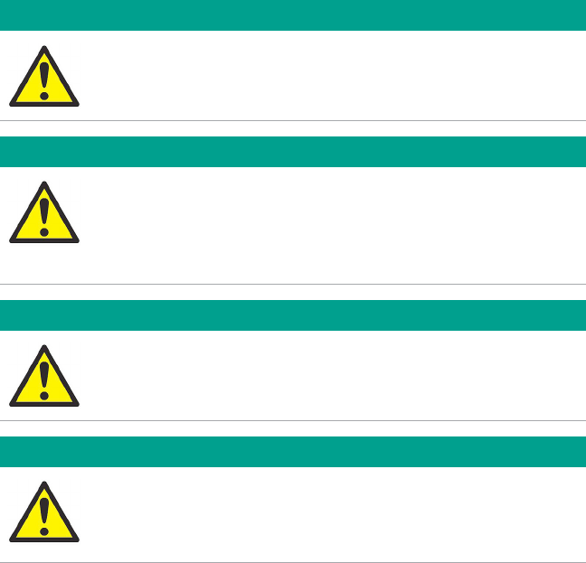
3.1 Safety issues
WARNING!
It is the responsibility of the user to make sure all local, county,
state and national codes, regulations, rules and laws related to
safety and safe operating conditions are met for each
installation.
WARNING!
It is the responsibility of the user to make sure the power,
analog and digital cables meet the published cable
specifications (see your User’s Manual).
3
3.2 Installation requirements
WARNING!
The PT900 flow transmitter can measure the flow rate of many
fluids, some of which are potentially hazardous. The use of
proper safety practices must be emphasized.
WARNING!
Be sure to follow all applicable local safety codes and
regulations for installing electrical equipment and working with
hazardous fluids or flow conditions. Consult company safety
personnel or local safety authorities to verify the safety of any
procedure or practice.
ATTENTION EUROPEAN CUSTOMERS!
To meet CE Mark and UL Mark requirements, all PT900 cables
must meet the published specifications (see the User’s
Manual).
CAUTION!
For CE compliance, the PT900 is classified as a battery-
powered device, and it is not to be operated with the AC power
adapter connected. To comply with CE certification, unplug the
AC power adapter before operating the PT900.
4
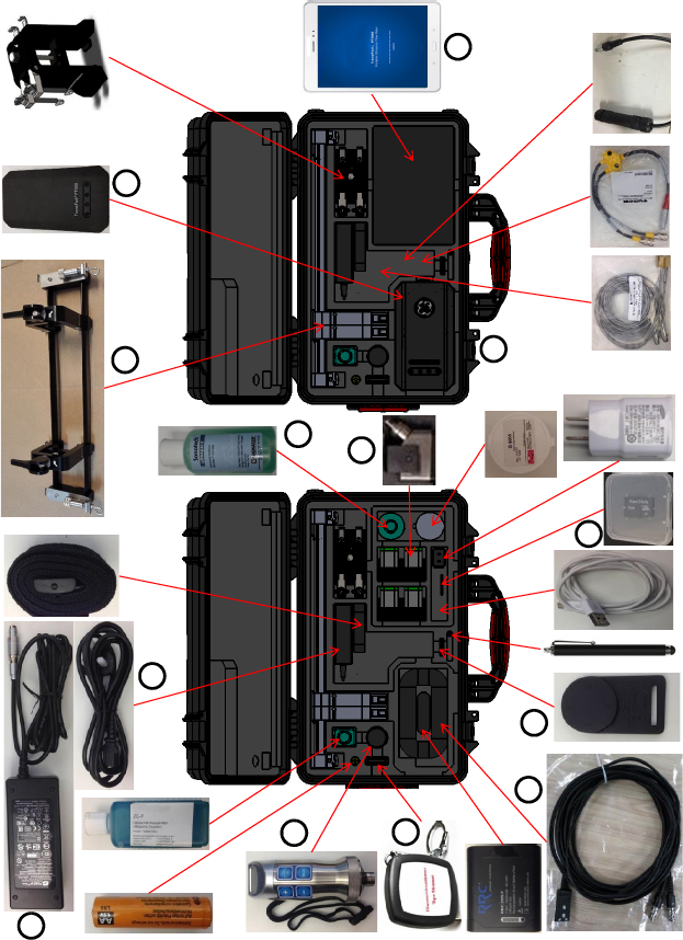
4.0 Unpacking the PT900 system
Before removing the PT900 system from its carrying case (see the optional
hard shell carrying case in Figure 1 on page 5), inspect the contents of the
case carefully. Before discarding any of the packing materials, account for
all components and documentation listed on the packing slip. If anything is
missing or damaged, contact Panametrics Customer Care immediately for
assistance.
Because the PT900 system may be ordered in many different configurations,
the following packing list is shown only as a typical example:
1. Transducers (2)
2. Clamping Fixture
3. Transducer Cables
4. Transmitter
5. Tablet
6. Tablet Power Cord
7. SD Card
8. Case
9. PT900 Power Supply
10. OD Tape
11. Couplant
12. PT900 Mounting Strap w/Magnet
13. Temperature Transmitter
14. Thickness Gauge
15. Documentation
In addition to the standard components, the following optional components
are available for use with the PT900 system:
• Energy kit with an RTD module and an RTD cable for connection to the
PT900 transmitter
• An AIO cable with cabling box
• A DIO cable with cabling box
• A battery charger
• A transducer extension cable up to 100 ft long
• A 48” chain for the clamp-on fixture
5
4.0 Unpacking the PT900 system (cont.)
Figure 1: PT900 System in Hard Carrier Case
9
4
2
6
11
1
14 10
5
8
12
3
7

6
5.0 Charging the PT900 transmitter
and tablet
Before proceeding, make sure that both the PT900 Transmitter and the
Tablet are fully charged. The AC power adapter is shipped in the carry case.
If either the transmitter or the tablet cannot be powered On after charging,
contact your Panametrics representative for assistance.
To charge the transmitter, use the AC power adapter provided. Charging
will occur whether the PT900 is On or Off, and the battery LEDs indicate
the battery charging status. Charging a fully-depleted battery pack to full
charge may take up to 3 hours.
6.0 Installing the PT900 tablet app
This section describes how to install the PT900 APP on your Android tablet.
6.1 Obtaining the PT900 android app
Obtain the PT900 APP from one of the following locations:
• Google Play Store (free download):
Set up a free account in Google Play Store. Search for the TransPort
PT900 APP and install it on your tablet.
• QR Code or Panametrics Website (free download):
Either Scan the QR Code in Figure 2 below or download the latest
version of the APP directly from the Panametrics website at the
following URL: https://www.bakerhughesds.com/panametrics/
portable-flow-meters
Figure 2: QR Code
• The SD card supplied with your PT900 system:
Plug the SD card directly into your tablet, and select the APK file
from the SD folder.
Note: Check the Panametrics website for the latest version.
7
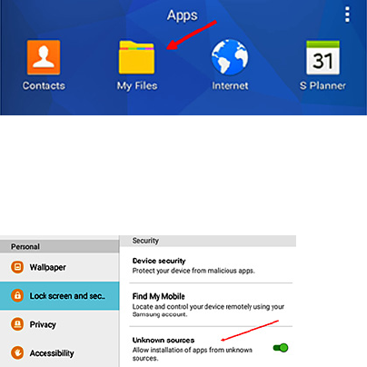
6.2 Installing the app on the tablet
To install the APP, complete the following steps:
1. Open the “My Files” folder on the tablet screen (see Figure 3 below) and
select the APP from the SD folder.
Figure 3: The “My Files” Folder
2. If the APP is from an SD card or the Panametrics website, enable the
security option in the tablet’s settings (see Figure 4 below) to allow the
installation of software from “Unknown sources” for this installation only.
Figure 4: Security Settings
8
6.2 Installing the app on the tablet (cont.)
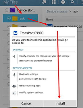
3. Click on the APK file, and the Android operating system will verify the
checksum and signature for the file. Depending on whether this is an
initial installation or an update installation, you will see a screen similar
to Figure 5 below. Click “Install” to begin the installation.
Figure 5: Initial Installation Screen
9
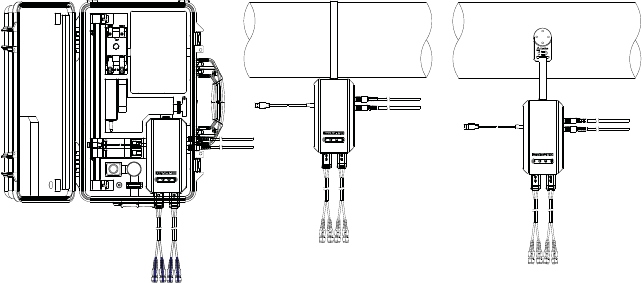
7.0 Mounting the PT900 transmitter
The PT900 portable transmitter is housed in a durable rubberized enclosure
suitable for indoor or outdoor use. It can be placed in the optional hard shell
carrier case, mounted on the pipe with the soft strap or mounted on the
pipe with the magnet clamp (see Figure 6 below).
Note: The pipe temperature must be between -20°C and about +40°C to
safely use the soft strap or magnetic clamp for mounting the transmitter.
Hard Carrier Case
Soft Strap Magnetic Clamp
Figure 6: PT900 Transmitter Mounting Options
8.0 Pairing the tablet and transmitter
To pair the tablet and the transmitter via the wireless Bluetooth connection:
1. Make sure the Tablet is turned On, the PT900 APP is installed, and the
battery is fully charged.
2. Make sure the Transmitter battery pack is fully charged, and turn the
Transmitter On by pressing and holding the Pwr button for more than
three seconds. The Green Power LED will indicate that the power is On.
3. After the APP finishes loading, the default Transmitter list is displayed.
During initial installation, this list is empty. To connect to a new PT900
transmitter, click SCAN (see the red arrow in Figure 7 on page 10) and the
APP will search for all available transmitters via Bluetooth.
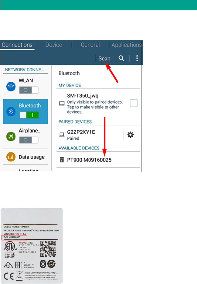
4. After the scan has been completed, any new transmitters which were
found are listed in the AVAILABLE DEVICES section of the tablet screen
(see the red arrow in Figure 7 on page 10). Click on your transmitter to
pair it with the tablet.
10
8.0 Pairing the tablet and the transmitter
(cont.)
IMPORTANT
Although Bluetooth is installed in many devices, the PT900 APP is designed
to filter out all devices except those with names of the form PT900-
Mxxxxxxxx.
Figure 7: Available Devices List
Note: In the above step, your PT900 transmitter is identified by the serial
number on its label (see Figure 8 below).
Figure 8: Transmitter Serial Number
Click Here
11
8.0 Pairing the tablet and the transmitter
(cont.)
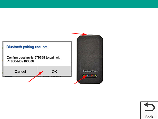
5. During the pairing process, PT900 security features require the user to
confirm the pairing (see Figure 9 below). When the Bluetooth pairing
request appears on the tablet, a random passkey will be generated. You
may ignore the random passkey and click OK to continue. Then, confirm
that the blue LED on the transmitter is flashing and click the transmitter
power button.
IMPORTANT
The pairing is completed only after it is confirmed at both the tablet and
the transmitter. Otherwise, the pairing will fail.
3. Click Button
1. Click Here 2. Blue Flashing LED
Figure 9: Confirm Pairing
6. Click the BACK button (shown at right) on the Android tablet to
return to the PT900 APP. Then, select your PT900 transmitter in
the TRANSMITTERS PAIRED list and click NEXT to open the Main
Menu.
12
9.0 Initial programming
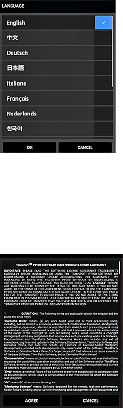
9.1 Selecting the app language
When opening the Tablet APP for the first time, the screen in Figure 10 below
is shown. Select the desired language for the APP and click OK.
Figure 10: APP Language Options
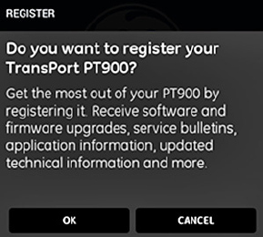
9.2 Accepting the license agreement
The PT900 License Agreement screen (see Figure 11 below) is shown next.
Read the agreement carefully and then click AGREE to continue with the APP
installation or click CANCEL to stop the APP installation.
Figure 11: PT900 License Agreement
13
9.3 Registering the PT900
At the Registration screen (see Figure 12 below), click OK to register your
PT900 or click CANCEL to skip the registration.
Note: If you skip the registration, the screen will popup as a reminder the first
five times you launch the APP and then it will never appear again.
Figure 12: PT900 Registration
14
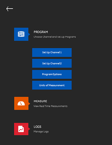
9.4 The app main menu
Note: As an alternative to the Main Menu described below, you may use the
Slide Menu shown on the next page.
The main menu screen shown in Figure 13 below is the starting point for all
PT900 programming steps. At a minimum, to get your PT900 system up and
running to begin taking measurements, program the following menus:
• “Selecting the Units of Measurement” on page 16
• “Activating Channel 1” on page 17
• “Programming the PIPE Menu” on page 18
• “Programming the FLUID Menu” on page 19
• “Programming the TRANSDUCERS Menu” on page 20
• “Programming the PLACEMENT Menu” on page 21
Figure 13: The APP Main Menu
15
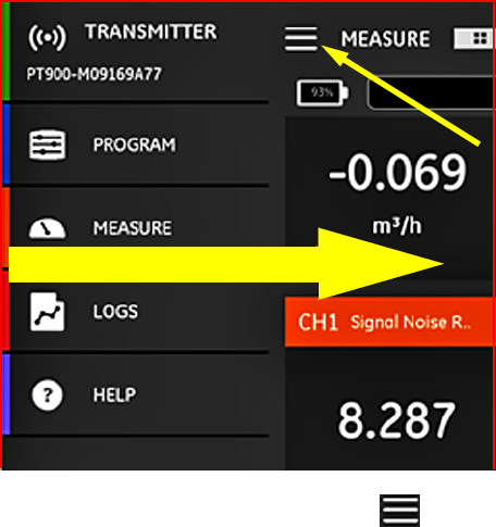
9.5 The app slide menu
As an alternative to the Main Menu discussed in the previous section, you
may use the Slide Menu shown in Figure 14 below.
Click Here
Swipe from left edge to right
Figure 14: APP Slide Menu Screen
To access the Slide Menu, either click the icon in the top left corner of
the screen or swipe across the screen from the left edge to the right. The
available options in the APP Slide Menu are:
• PROGRAM, which is used for selecting and configuring a channel.
• MEASURE, which is used for viewing real time measurements, error reports
and diagnostics information.
• LOGS, which is used for setting up log files and managing logs stored in
the PT900 transmitter.
• HELP, which is used for accessing detailed information and instructions for
your PT900 system.
16
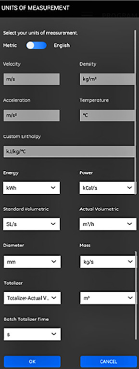
9.6 Selecting the units of measurement
Click the Units of Measurement button in Figure 13 on page 14 to open the
UNIT OPTIONS menu shown in Figure 15 below. This menu allows the user to
select the measurement units displayed by the PT900 in all of its display
screens.
Note: Because the choice of Metric or English units is reflected in all other
menu screens, this menu should be programmed first.
Figure 15: The Units of Measurement Menu
17
9.6 Selecting the units of measurement
(cont.)
To program the Units of Measurement options, complete the following steps:
1. Move the slide switch at the top of the menu to either Metric or English to
select the desired PT900 global measurement units system.
2. Based on your selection above, the units for all of the PT900
measurement parameters will be automatically populated with default
units.
a. Some of the parameters have only one units of measure choice
available. The text boxes for these parameters are grayed out, and the
default units cannot be changed.
b. Some of the parameters have multiple units of measure choices
available. The text boxes for these parameters are active, and the
default units can be changed by opening the drop-down list and
selecting the desired units.
3. After you have completed your programming, click the OK button to save
your choices or click the CANCEL button to discard the changes.
9.7 Activating Channel 1
Click the Setup Channel 1 button in Figure 13 on page 14 to open the Channel
1 menu shown in Figure 16 on page 18. At the top of the menu, slide the
toggle switch to change the channel status from Off to On.
18
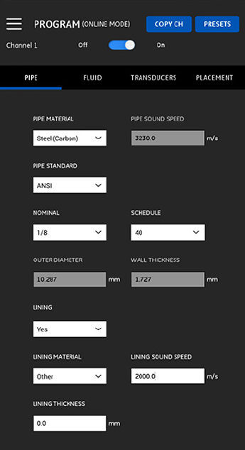
9.8 Programming the PIPE menu
Use the PIPE menu (see Figure 16 below) to specify all pipe parameters, to
ensure accurate flow rate measurements. For each of the menu options,
select an option from the drop-down list or enter the appropriate value for
your site.
Note: Refer to your user’s manual for detailed instructions on each option.
Figure 16: Channel 1 - PIPE Menu
19
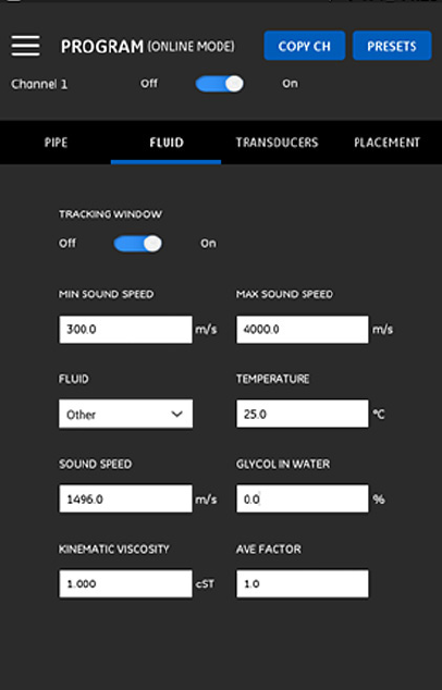
9.9 Programming the FLUID menu
Use the FLUID menu (see Figure 17 below) to specify all fluid parameters, to
ensure accurate flow rate measurements. For each of the menu options,
select an option from the drop-down list or enter the appropriate value for
your site.
Note: Refer to your user’s manual for detailed instructions on each option.
Figure 17: Channel 1 - FLUID Menu
20
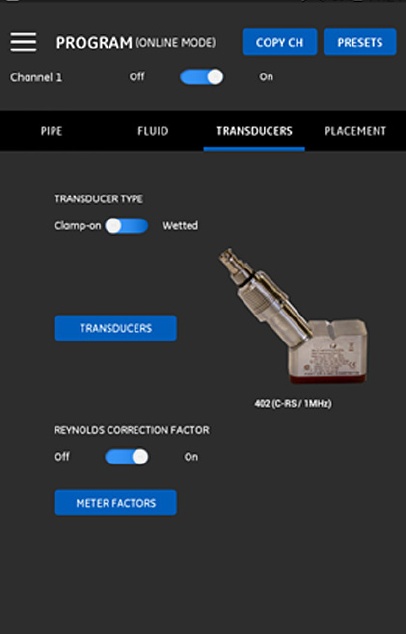
9.10 Programming the TRANSDUCERS menu
Use the TRANSDUCERS menu (see Figure 18 below) to specify all transducer
parameters, to ensure accurate flow rate measurements. For each of the
menu and sub-menu options, select an option from the drop-down list or
enter the appropriate value for your site.
Note: Refer to your user’s manual for detailed instructions on each option.
Figure 18: Channel 1 - TRANSDUCER Menu
21
9.11 Programming the PLACEMENT menu
The PLACEMENT menu allows the user to configure the mounting method
of the transducers, based on the programmed information in the
TRANSDUCERS menu (see “Programming the TRANSDUCERS Menu” on page
20).
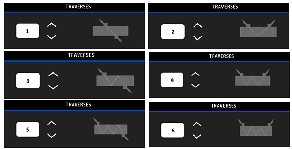
9.11.1 Viewing the traverse configuration
For CLAMP-ON transducers, one of the six possible TRAVERSE configurations
shown in Figure 19 below is displayed, as appropriate for your programmed
transducer information. Typically, a two-traverse installation is used.
Figure 19: Clamp-On Traverse Configurations
22
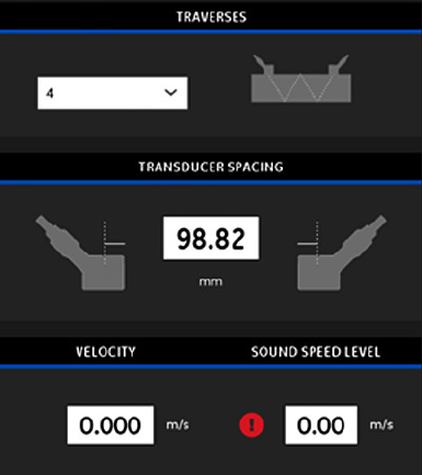
9.11.2 Viewing the transducer spacing
The TRANSDUCER SPACING screen (see Figure 20 below) shows the value
calculated by the PT900 for the correct distance between the upstream and
downstream transducers, based on your programmed data. This value is
used when installing your transducer clamping fixture on the pipe.
Figure 20: Transducer Spacing Value
23
10.0 Installing the transducers
To install the Transducers, complete the following steps:
1. Select a clamp-on fixture mounting location on the pipeline which
meets the following requirements:
• A straight pipe run of at least 10 nominal pipe diameters (with no
fittings or bends) before the upstream transducer
• A straight pipe run of at least 5 nominal pipe diameters (with no
fittings or bends) after the downstream transducer
• A clearance of at least 6” from the outer edge of each end piece to
the nearest joint, welding or flange in the pipeline
2. Mount the Clamp-On Fixture on the pipe (not provided) in the selected
location, and set the Transducer Spacing to the value calculated by the
APP (see Figure 20 on page 22).
3. Mount the transducers into the clamp-on fixture.
4. Connect the transducers to the transmitter with the cables provided.
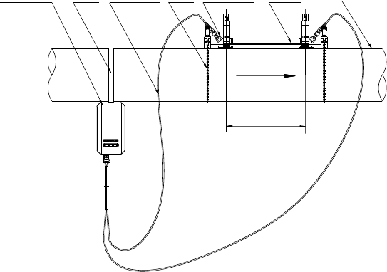
For reference, a completed PT900 installation is shown in Figure 21 below.
PT900
Transmitter
Soft
Strap
Transducer
Cable
Chain
(x2)
Pair of CRR
Transducers
PT900
Fixture
Flow Direction
Spacing
Pipe (Not
Provided)
Important: Transducers shown
on top of pipe for clarity only.
Always mount on side of pipe!
Figure 21: Completed Example Installation
24
11.0 Taking measurements
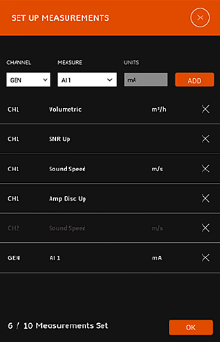
11.1 Setting up the measurements for
display
The PT900 APP can display up to 10 different variables at the same time.
To set up your display screen, click the EDIT button at the top right of the
measurement screen to open the SET UP MEASUREMENTS menu, as shown in
Figure 22 below.
Figure 22: Set Up Measurements Menu
To set up your display measurements, complete the following steps:
1. Open the drop-down list in the CHANNEL box and select either CH1, CH2,
Average or General as the channel to be displayed.
2. Open the drop-down list in the MEASURE box and select the desired
measurement variable from the list.
25
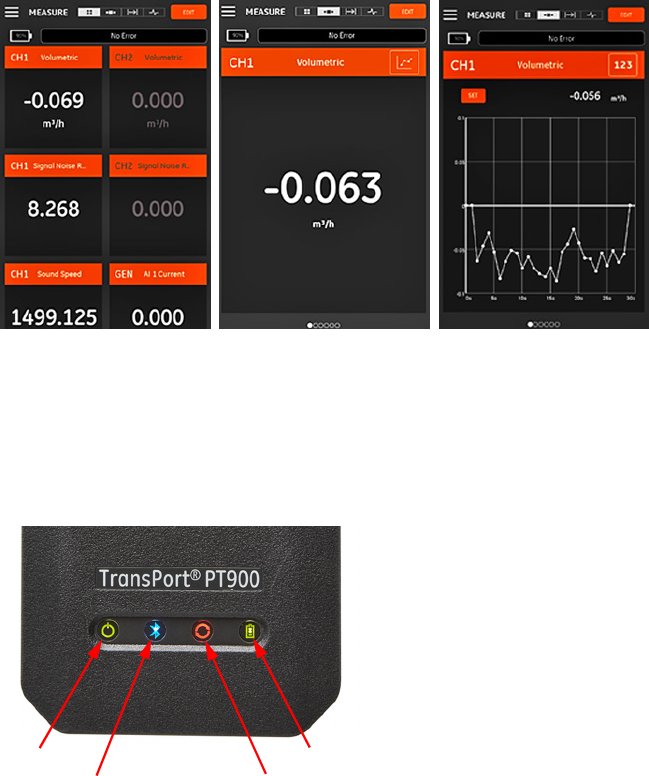
11.2 Selecting the measurement screen
After configuring the flow rate measurements in the previous section, select
either the multiple numeric, single numeric or graphical display screen
option (see Figure 23 below).
Figure 23: Measurement Screen Options
12.0 PT900 LED indicators
The four colored LEDs on the front of the PT900 transmitter (see Figure 24
below) provide real time information on the meter status. See the next page
for details.
Power
Bluetooth
Battery
Status
Figure 24: PT900 Transmitter LEDs
26
12.1 Power LED
• Solid Green light when the meter is powered On
• No light when the meter is Off
• Blinking Green light when the meter is in power save mode
12.2 Bluetooth LED
• Solid Blue light when Bluetooth®is linked to a transmitter
• Blinking Blue light when Bluetooth® is in the click-button to confirm pairing
process
• Solid Red light when the meter is on and Bluetooth® is idle or is not linked
to a transmitter
• No light when Bluetooth® is in configuration mode
12.3 Status LED
• Solid Green light when the meter is in measure mode without any errors
• Red light when an error occurs while the meter is in measure mode
• No light when the meter is in configure mode
12.4 Battery LED
• Solid Green light when the battery is fully charged (>99%), but the AC
adapter is connected
• Solid Green light when the battery level is high (>20%), but the AC adapter
is not connected
• Blinking Green light when the battery is not fully charged, but it is charging
with the AC adapter connected
• Red light when the battery level is low (≤20%) and the battery needs to be
charged immediately
• Blinking Red light when the battery level is low (≤10%) and the meter will be
out of power soon
• Light off when the meter is On, but the battery is completely discharged
and the AC adapter is connected
27

panametrics.com
Panametrics, a Baker Hughes Business, provides solutions
in the toughest applications and environments for
moisture, oxygen, liquid and gas flow measurement.
Experts in flare management, Panametrics technology
also reduces flare emissions and optimizes performance.
With a reach that extends across the globe, Panametrics’
critical measurement solutions and flare emissions
management are enabling customers to drive efficiency
and achieve carbon reduction targets across critical
industries including: Oil & Gas; Energy; Healthcare; Water
and Wastewater; Chemical Processing; Food & Beverage
and many others.
Join the conversation and follow us on LinkedIn
linkedin.com/company/panametricscompany
Copyright 2021 Baker Hughes Company. All rights reserved.
BH033C24 EN A (06/2021)
Customer support centers
Europe
Ireland
Sensing House
Shannon Free Zone East
Shannon, County Clare
Ireland
Tel: +353 61 61470200
E-mail:
Americas
U.S.A.
The Boston Center
1100 Technology Park Drive
Billerica, MA 01821
U.S.A.
Tel: +1 800 833 9438 (toll-free)
Tel: +1 978 437 1000
E-mail:
