PARTS & ACCESSORIES
Quick RefeRence Guide
The Beckett AquaSmart is an advanced boiler control designed for use on residential and light commercial
boiler systems. All models include the option of enabling Beckett HeatManager™ dynamic temperature reset
that, when selected, provides up to 20% fuel consumption savings. The control includes a backlit LCD digital
display with touch pad to easily program temperature limits, differentials, and other advanced options. The
AquaSmart also has memory storage of system history for help with diagnostics and troubleshooting.
Temperature Ranges and Differentials
High Limit Setting Range: 100 to 240°F (38 to 116°C)
High Limit Differential Range: 5 to 45°F (3 to 25°C)
Low Limit Setting Range: 100 to 220°F (38 to 104°C)
Low Limit Differential Range: 10 to 45°F (6 to 25°C)
Factory Range Stops available - consult factory
Environmental Ratings
Storage Temperature: -40 to +150°F (-40 to +65°C)
Operating Temperature: -4 to +150°F (-20 to +65°C)
Maximum Sensing Element Temperature: 250°F (121°C)
Relative Humidity: 5 to 85% RH, non-condensing and
non-crystallizing
○
○
○
○
○
○
○
○
○
Technical Specications
Electrical Ratings
Input Voltage: 120 Vac - 50/60 Hz.
Input Current: 0.1 A + B1 + C1 + ZC
MAX Input Current: 20A (Reduce to 15A if optional
power switch is used)
24 Vac Thermostat Anticipator Current: 0.1 Amp.
Burner Current Rating (B1):
7600A (oil): 7.4 A at 120 Vac FLA; 44.4 A inrush LRA.
7600B (gas): 1.25 A at 24 Vac; 30 VA (total load).
Circulator Current Rating (C1): 7.4 A at 120 Vac FLA;
44.4 A inrush LRA.
Zone Control Current Rating (ZC): 7.4 A at 120 Vac
FLA; 44.4 A inrush LRA.
Do Not Use This Control in an Application that is Not Within the Ratings
Listed in This Section. Improper Control Operation May Result.
Electrical Shock, Fire, Explosion and Burn Hazards
This control must be installed, adjusted and put into operation only by a trained, licensed, qualied
professional or service agency in accordance with the National Electric Code ANSI/NFPA 70 (Canada CSA
C22.1) state, local codes and authorities having jurisdiction.
The installer must carefully read and follow the installation and service instructions contained in this pamphlet and in
the owner’s manual. Make them available to the equipment owner, so they can be kept for future reference.
Please refer to the AquaSmart Owner’s Manual for more detailed instructions and advanced
programming options.
Approvals
Underwriters Laboratories Recognition to UL353, UL1998 for U.S. and Canada
Page 2
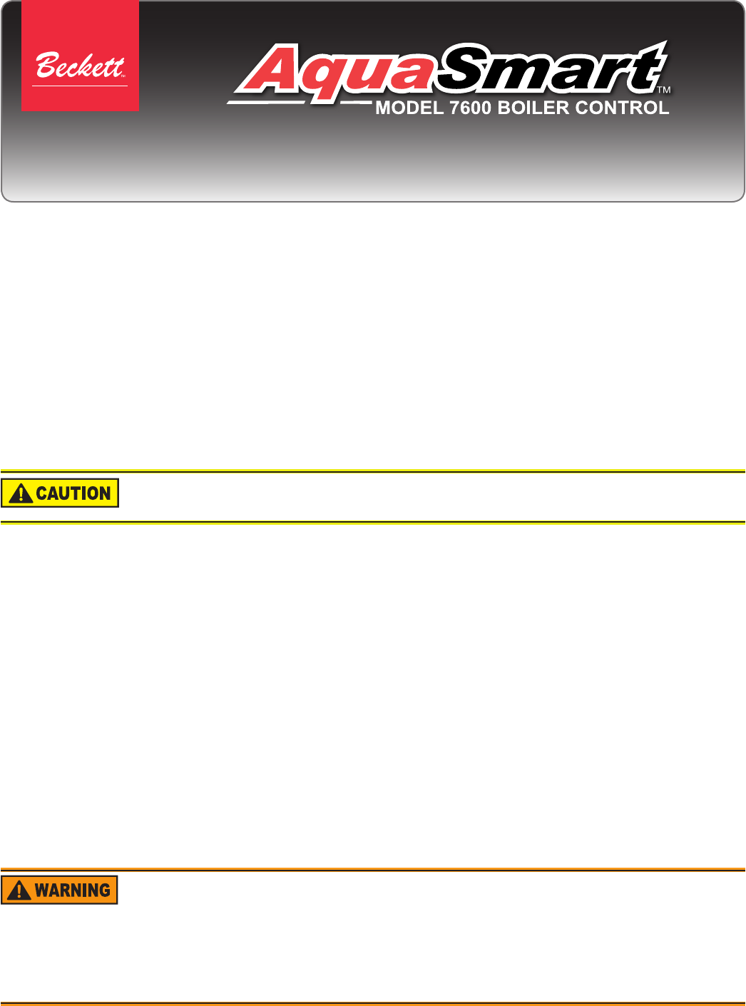
Figure 1 - Getting to know the AquaSmart 7600 Series Control
OEM Installation: When replacing an OEM-installed
AquaSmart, consult the appliance manufacturer’s wiring
diagrams and instructions for additional information.
Retrot Installation: The AquaSmart can be used to
replace most standard boiler temperature controls. For a
cross-reference of compatible replacements, refer to
Owner’s Manual.
There are two basic methods for mounting the AquaSmart
to the boiler.
Sensor/Immersion Well Mounting – This is the
most common method. If the existing well is not
suitable for any reason, a standard design aftermarket
immersion well with the proper dimensions can be
purchased from a HVAC distributor. The AquaSmart
can then be mounted in the typical way.
Surface Mounting – This is sometimes required
and is part of the AquaSmart base design. The base
has adequate clearance built-in to accommodate the
temperature sensor lead exiting the back of the
control. A 48” extension cable (Pt. No. 52120) can
be purchased separately for applications where
needed.
1.
2.
Installation
B. Temperature Low Limit
In any mode or screen other than an OPTION sub-
menu, press the “LOW LIMIT” key.
The temperature displayed is the current setting.
Use the “▲” and “▼” keys to select the desired
setting. Tap the button to increase or decrease the
temperature by 1°, or hold it to increase or decrease
the temperature by 5° at a time. For cold-start
operation, turn the low limit off by pressing the down
arrow key repeatedly until OFF is displayed.
IMPORTANT: To prevent ue gas condensation and
reduce fatigue caused by thermal cycling on
conventional (non-condensing) boilers, the LOW
LIMIT set point should be 150° F or above.
NOTE: Boiler manufacturer’s temperature
requirements supersede this recommendation.
Press the “ENTER (RESET)” key. Conrm the
setting by pressing “ENTER (RESET)” again if the
value is correct, or “CANCEL (BACK)” if it is not.
C. Temperature High Limit Differential
In any mode or screen other than an OPTION sub-
menu, press the “HIGH DIFF” key.
The temperature displayed is the current setting.
Use the “▲” and “▼” keys to select the desired
setting. Tap the button to increase or decrease the
temperature by 1°, or hold it to increase or decrease
the temperature by 5° at a time.
Press the “ENTER (RESET)” key. Conrm the
setting by pressing “ENTER (RESET)” again if the
value is correct, or “CANCEL (BACK)” if it is not.
D. Temperature Low Limit Differential
In any mode or screen other than an OPTION sub-
menu, press the “LOW DIFF” key.
The temperature displayed is the current setting.
Use the “▲” and “▼” keys to select the desired
setting. Tap the button to increase or decrease the
temperature by 1°, or hold it to increase or decrease
the temperature by 5° at a time.
Press the “ENTER (RESET)” key. Conrm the
setting by pressing “ENTER (RESET)” again if the
value is correct, or “CANCEL (BACK)” if it is not.
1.
2.
3.
1.
2.
3.
1.
2.
3.
To ensure smooth appliance operation, the AquaSmart
requires a separation between the High and Low limits no
less than the greater differential plus 5°F.
For example: If the High Limit is set to 180°F, the High Diff
to 20°F, and the Low Diff to 10°F, the control will not allow
a Low Limit above 155°F (180°F - 20°F [the greater of the
two differentials] - 5°F = 155°F).
A. Temperature High Limit
In any mode or screen other than an OPTION sub-
menu, press the “HIGH LIMIT” key.
The temperature displayed is the current setting.
Use the ▲ and ▼ keys to select the desired setting.
Tap the button to increase or decrease the
temperature by 1°, or hold it to increase or decrease
the temperature by 5° at a time.
Press the “ENTER (RESET)” key. Conrm the
setting by pressing “ENTER (RESET)” again if the
value is correct, or “CANCEL (BACK)” if it is not.
1.
2.
3.
Basic Programming
Sensor Jack
Touch Pad
Clamping Screw For Sensor
Disconnect Switch (Optional)
TW/TR Terminals
Communication Port
Sensor Mount
Page 3
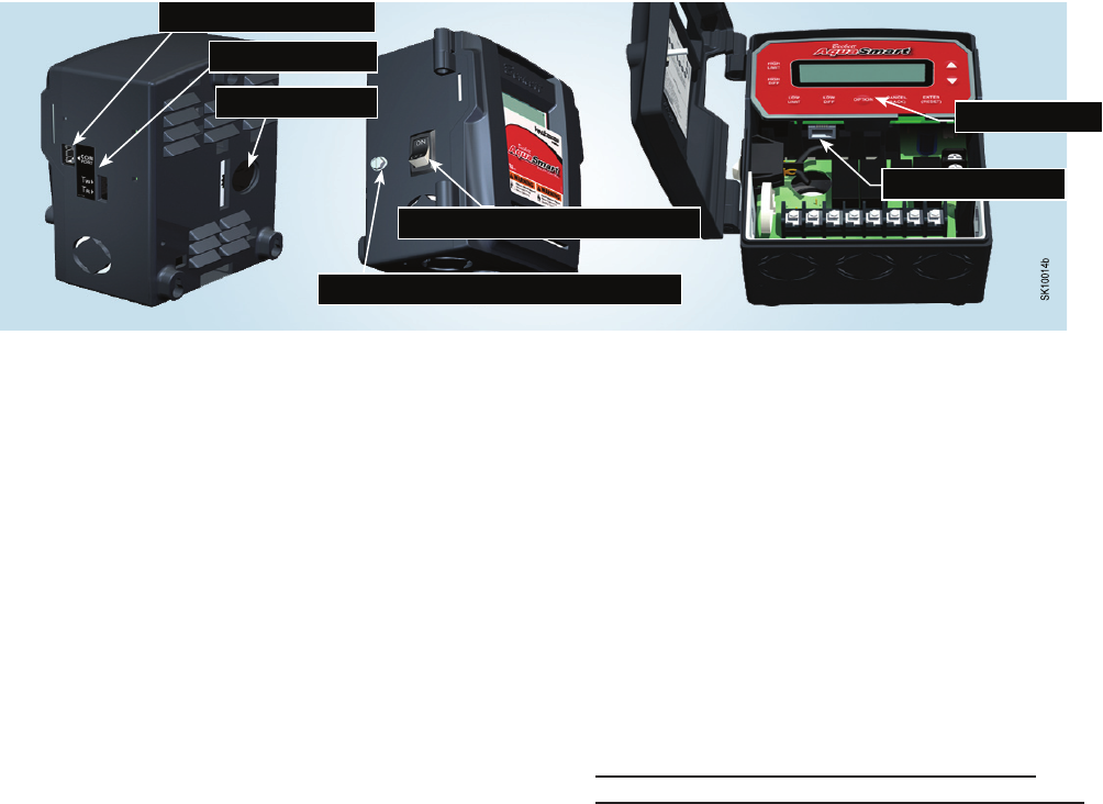
Figure 2 - 7600A/B single-zone connections with or without a tankless coil
Control Wiring:
1. Set “DHWP OFF” (default, see programming
section of the Owner’s Manual for further
instructions)
2. Set “C1 on TT” (default, see programming
section of the Owner’s Manual for further
instructions)
LOW VOLTAGE
THERMOSTAT
L2 L1 C1 C2 ZC ZR B1 B2
P1
CIRCULATOR
120 VAC
120 VAC
NEUTRAL WHITE
HOT
SERVICE
SWITCH
BLACK
7600A:
120 VAC BURNER OR
GAS IGNITION SYSTEM
7600B:
24 VAC GAS
IGNITION SYSTEM
TW
TR
WHITE
RED
BLACK
WHITE
SK10019
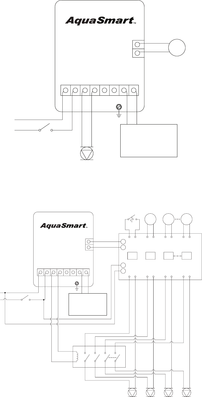
Figure 3 - 7600A/B multi-zone connections with Indirect Domestic Hot Water (DHW)
Control Wiring Option: Utilizing a Zone Panel
1. Set “DHWP OFF” (default, see
programming section of the Owner’s
Manual for further instructions) DHW Zone
priority will be determinedby the zone
panel.
2. Set “C1 on TT” (default, see programming
section of the Owner’s Manual for further
instructions)
3. Circulator-on delay will affect all zones.
Circulator-off delay will have no effect. If Circulator-
on delay is not desired, remove the n-pole contactor
and wire the circulators directly to the zone panel.
L2 L1 C1 C2 ZC ZR
B1
B2
TR
TW
SK10036
ZONE
PANEL
SERVICE
SWITCH
NEUTRAL
HOT
120 VAC
BLACK
WHITE
X
X
L1
L2
Z1 Z2 Z3 Zn
CIRCULATOR
120 VAC
P1
P2
CIRCULATOR
120 VAC
P3
CIRCULATOR
120 VAC
Pn
CIRCULATOR
120 VAC
n-POLE
CONTACTOR
120 VAC COIL
DHW
AQUASTAT
ZONE 1
LOW
VOLTAGE
THERMOSTAT
ZONE 2
LOW
VOLTAGE
THERMOSTAT
ZONE n
LOW
VOLTAGE
THERMOSTAT
END
SWITCH
7600A:
120 VAC BURNER OR
GAS IGNITION SYSTEM
7600B:
24 VAC GAS
IGNITION SYSTEM

Form No. 61757 Rev. 0, Printed in USA 09/09
PARTS & ACCESSORIES
USA: P.O. Box 1289
●
Elyria, OH 44036
●
Phone: 800-OIL-BURN (800-645-2876)
Canada: R.W. Beckett Canada, Ltd.
●
Unit #3, 430 Laird Road
●
Guelph, Ontario N1G 3X7
www.beckettcorp.com
Limited
WARRANTY
For Residential, Commercial and Specialty Burners
The R. W. BECKETT CORPORATION (“Beckett”) warrants to persons who purchase its Beckett burners from Beckett for resale or for incorpora-
tion into a product for resale (“Customers”) that its equipment is free from defects in material and workmanship under normal use and service
for 60 months from the date of manufacture for Residential Burners and 18 months from the date of manufacture for Commercial and Specialty
Burners. Residential burner models include: AF, AFG, AFII, NX, SF, SR and SMG. Commercial burner models include: CF375, CF500, CF800,
CF1400, CF2300A, CF2500, CF3500A, CG10, CG15, CG25 and CG50. Specialty burner models include: ADC, ADCP, ARV, SDC and SM. The
provisions of this warranty are extended to individual major burner components as follows:
a) 60 months from date of manufacture for all Beckett-branded major components, except for 12 Vdc components.
b) 18 months from date of manufacture for all non-Beckett-branded major components and Beckett branded 12 Vdc components.
c) 12 months from date of manufacture for all Beckett-branded tools, such as the GeniSys Display.
Note: Normal service items found to be defective upon receipt by the customer are covered by this warranty.
THIS WARRANTY DOES NOT EXTEND TO EQUIPMENT SUBJECTED TO MISUSE, NEGLECT, OR ACCIDENT: NOR DOES THIS WAR-
RANTY APPLY UNLESS THE PRODUCT COVERED BY IT IS PROPERLY INSTALLED BY A QUALIFIED, COMPETENT TECHNICIAN,
WHO IS LICENSED WHERE STATE AND LOCAL CODES REQUIRE, AND WHO IS EXPERIENCED IN MAKING SUCH INSTALLATIONS,
IN ACCORDANCE WITH THE LATEST EDITION OF NFPA NO. 31 OF THE NATIONAL FIRE PROTECTION ASSOCIATION, THE LATEST
EDITION OF THE NATIONAL FUEL GAS CODE (NFPA NO. 54) AND IN ACCORDANCE WITH ALL APPLICABLE LOCAL, STATE AND
NATIONAL CODES HAVING JURISDICTIONAL AUTHORITY.
Equipment, which is defective in material or workmanship and within the warranty period, may be returned for credit as follows: Beckett Burners,
Beckett-branded major components and non-Beckett-branded major components that came as original equipment on a Beckett burner or were
sold as a replacement part by Beckett should be returned, freight prepaid, to Beckett’s home of ce. Credit will be issued to the customer unless
the returned equipment is determined by Beckett to be out of warranty or damaged by user, in which case the equipment will be scrapped.
Note: Beckett is not responsible for any labor cost for removal and replacement of equipment.
THIS WARRANTY IS LIMITED TO THE PRECISE TERMS SET FORTH ABOVE, AND PROVIDES EXCLUSIVE REMEDIES EXPRESSLY IN
LIEU OF ALL OTHER REMEDIES, AND IN PARTICULAR THERE SHALL BE EXCLUDED THE IMPLIED WARRANTIES OF MERCHANTABIL-
ITY AND FITNESS FOR A PARTICULAR PURPOSE. IN NO EVENT WILL BECKETT BE LIABLE FOR ANY INCIDENTAL OR CONSEQUEN-
TIAL DAMAGE OF ANY NATURE. Beckett neither assumes nor authorizes any person to assume for Beckett any other liability or obligation in
connection with the sale of this equipment, Beckett’s liability and Customer’s exclusive remedy being limited to credit as set forth above.
R.W. BECKETT CORPORATION
P.O. Box 1289 Elyria, Ohio 44036
Form No. 61545 R07
